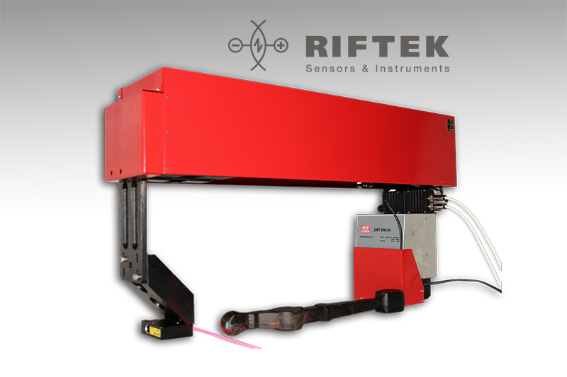
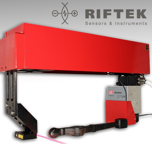
| Parameter | Value |
|---|---|
| Scanning range Y-axis (mm) | 370 |
| Scanning range Z-axis (mm) | 135 |
| Scanning range X (start of measurement, Z-axis) (mm) | 45 |
| Scanning range X (end of measurement, Z-axis) (mm) | 70 |
| Measurement accuracy, X, Z axes, (um) | ±50 |
| Measurement accuracy, Y axis, (um) | ±20 |
| Sampling rate, profiles/s | 250 |
| Speed (mm/s) | |
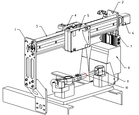
| Parameters under control | see point 10.1.2 |
| Dimension (mm) | 730x415x180 |
| Weight (kg) | 40 |
| Power Supply |
Alternating-current mains with sampling rate (50 ±
1)Hz, norminal power 220 with allowable stress ±10% |
| Power Consumption (W) | 300 |
| Environment Conditions |
Environment temperature: +1...+35°С Relative humidity 25...65% |
 기계는 다음과 같이 작동
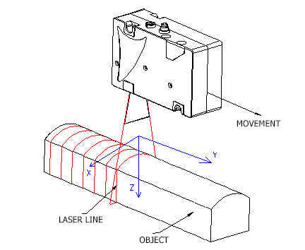 결과는 설정된 프로파일 좌표 (X, Y, Z)를 갖는 Point Cloud 형식의 3D
컴퓨터 모델.
결과는 설정된 프로파일 좌표 (X, Y, Z)를 갖는 Point Cloud 형식의 3D
컴퓨터 모델.